
This article will introduce the design ideas and processing process of plastic lunch box cover in detail, and the structure of plastic parts, materials for a comprehensive analysis, reasonable design of mold technology.
Key words: injection mold; Lunch box. Molding process
Part One:Process analysis of plastic parts and primary selection of injection machine
1.1 Raw materials and performance analysis of plastic lunch box
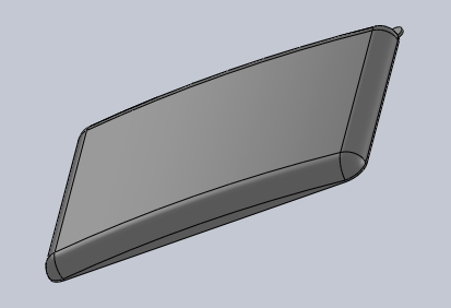
This plastic lunch box is a common plastic product in daily life, mainly used to hold food. Considering the particularity of its use, comprehensive analysis of the performance of various plastics, the choice of material for polypropylene (PP).
Polypropylene (PP plastic) is a kind of high density, no side chain, high crystallization of linear polymer, has excellent comprehensive properties. When not colored, white translucent, waxy; Lighter than polyethylene. Transparency is also better than polyethylene. In addition, the density of polypropylene is small, specific gravity of 0.9~0.91 grams/cubic centimeter, yield strength, elasticity, hardness and tensile, compressive strength are higher than polyethylene. Its molding temperature is 160~220℃, can be used in about 100 degrees, and has good electrical properties and high frequency insulation is not affected by humidity. Its water absorption rate is lower than polyethylene, but easy to melt body rupture, long-term contact with hot metal is easy to decompose, aging. The fluidity is good, but the forming shrinkage rate is 1.0~2.5%, the shrinkage rate is large, which is easy to lead to the shrinkage hole, dent, deformation and other defects. Polypropylene cooling speed is fast, pouring system and cooling system should be slowly cooling, and pay attention to control the forming temperature. The wall thickness of plastic parts should be uniform to avoid lack of glue and sharp Angle to prevent stress concentration.
1.2 Analysis of molding process of plastic lunch box
1.2.1. Structural analysis of plastic parts
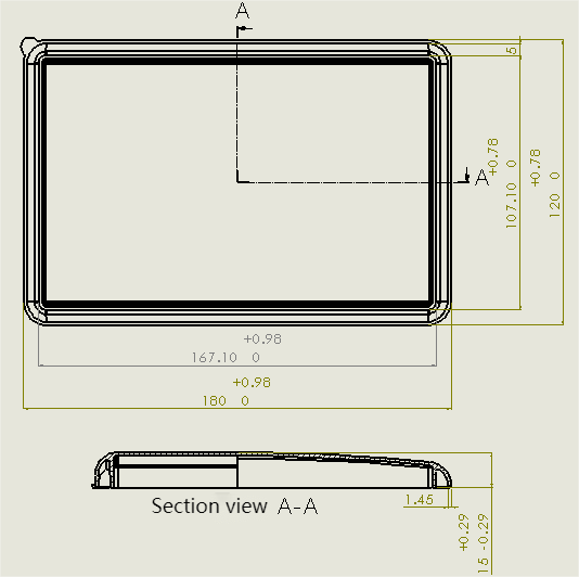
The recommended wall thickness of polypropylene small plastic parts is 1.45mm; The basic size of the lunch box is 180mm×120mm×15mm; Take the inner wall size of the lunch box cover: 107mm; The difference between the inner and outer walls is: 5mm; The rounded corner of the outer wall is 10mm, and the rounded corner of the inner wall is 10/3mm. One corner of the box cover has an annular boss with a radius of 4mm. Because the plastic parts are thin-walled containers, in order to prevent the lack of stiffness and strength caused by plastic parts deformation, so the top of the plastic parts is designed as a 5mm high arc circle.
1.2.2. Dimensional precision analysis of plastic parts
The two dimensions of the lunch box cover have accuracy requirements, namely 107mm and 120mm, and the accuracy requirement is MT3. Since the external dimension of the plastic parts is affected by the tolerance of the dimensions of the movable part of the mold (such as the flying edge), the tolerance type is selected as grade B. If tolerance level is not required, MT5 is selected.
1.2.3. Surface quality analysis of plastic parts
The surface accuracy of the lunchbox cover is not high, and the surface roughness Ra is 0.100~0.16um. Therefore, the single parting surface cavity injection mold of the gate runner can be used to ensure the surface accuracy.
1.2.4. Material properties and volume and quality of plastic parts
Query the material properties of PP plastic (including elastic modulus, Poisson’s ratio, density, tension strength, thermal conductivity and specific heat) in SolidWorks, and use SolidWorks software to calculate the data of plastic parts (including weight, volume, surface area and center of gravity).
1.3 Determine the molding process parameters of plastic parts
In the process of injection molding, the temperature of the cylinder and nozzle will affect the plasticization and flow of plastic, the temperature of the mold will affect the flow and cooling of plastic shaping, the pressure in the process of injection molding will directly affect the plasticization of plastic and plastic parts quality. Production in the case of ensuring the quality of plastic parts will try to shorten the molding cycle of plastic parts, which injection time and cooling time have a decisive impact on the quality of plastic parts.
Questions to consider when designing:
1) Appropriate use of stabilizers, lubricants to ensure the process performance of PP plastic and the use of plastic parts.
2) Shrinkage, indentation, deformation and other defects should be prevented during design.
3) Due to the fast cooling speed, pay attention to the heat dissipation of the pouring system and the cooling system, and pay attention to the control of the forming temperature. When the mold temperature is lower than 50 degrees, the plastic parts will not be smooth, there will be poor welding, leaving marks and other phenomena; More than 90 degrees is prone to warp deformation and other phenomena.
4) The wall thickness of plastic parts shall be uniform to avoid stress concentration.
1.4 Model and specification of injection molding machine
According to the molding process parameters of plastic parts, the initial choice of domestic G54-S200/400 model injection molding machine,
Part Two:Structural design of plastic lunch box cover injection mold
2.1 Determination of the parting surface
The basic shape and demoulding condition of plastic parts should be considered when selecting the parting surface. The design principles of the parting surface are as follows:
1. The parting surface should be selected at the maximum contour of the plastic part
2. The selection of parting surface should be conducive to the smooth demoulding of plastic parts
3. The selection of parting surface should ensure the dimensional accuracy and surface quality of plastic parts and their use requirements
4. The selection of parting surface should be conducive to the processing and simplification of the mold
5. Minimize the projection area of the product in the direction of clamping
6. Long core should be placed in the direction of die opening
7. Selection of parting surface should be conducive to exhaust
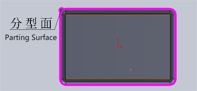
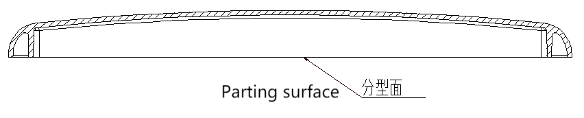
To sum up, in order to ensure the smooth demoulding of plastic parts and the technical requirements of plastic parts and simple manufacturing of the mold, the parting surface is selected as the lower surface of the lunch box cover. As shown in Figure below:
2.2 Cavity number determination and configuration
According to the design requirements of plastic parts design manual, plastic parts geometric structure characteristics and dimensional accuracy requirements and economic requirements of production, determine the use of a mold a cavity.
2.3 Design of pouring system
This design adopts ordinary pouring system, and its design principles are as follows:
Keep the process short.
Exhaust should be good,
Prevent core deformation and insert displacement,
Prevent the warping deformation of plastic parts and the formation of cold scars, cold spots and other defects on the surface.
2.3.1 Main channel design
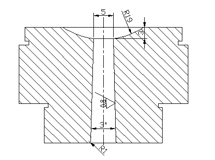
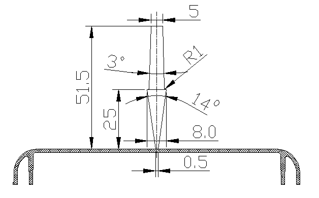
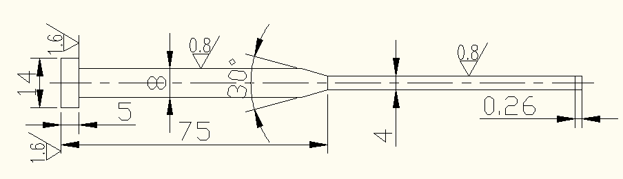
The main channel is designed to be conical, and the cone Angle α is 2O-6O, and α=3o. The surface roughness of the flow channel Ra≤0.8µm, the outlet of the main channel is the fillet transition, in order to reduce the resistance of the material flow to the transition, the fillet radius r=1~3mm, is taken as 1mm. The main channel design is as follows;
The structure of the gate sleeve is designed into two parts using the gate sleeve and the positioning ring, which is fixed on the fixed die seat plate in the form of a step.
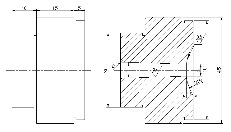
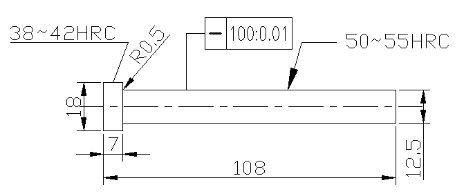
The diameter of the small end of the gate sleeve is 0.5~1mm larger than that of the nozzle, which is taken as 1mm. Since the front of the small end is a sphere, its depth is 3~5mm, which is taken as 3mm. Since the sphere of the nozzle of the injection machine contacts and fits the mold at this position, the diameter of the sphere of the main channel is required to be 1~2mm larger than that of the nozzle, which is taken as 2mm. The use form and parameters of the gate sleeve are shown below:
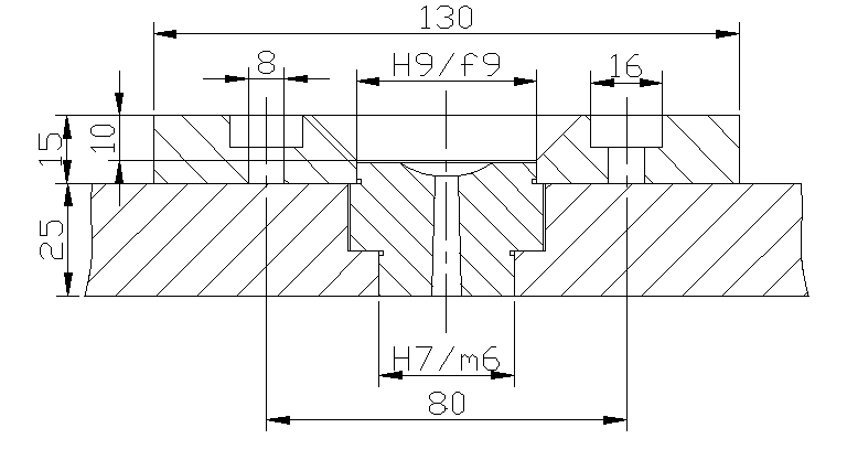
H7/m6 transition fit is adopted between the gate sleeve and the template, and H9/f9 fit is adopted between the gate sleeve and the positioning ring. The positioning ring is inserted into the positioning hole of the fixed template of the injection machine during the installation and debugging of the mold, which is used for the installation and positioning of the mold and the injection machine. The outer diameter of the positioning ring is 0.2mm smaller than the positioning hole on the fixed template of the injection machine, so it is 0.2mm. The fixed form of the gate sleeve and the size of the positioning ring are shown below:
2.3.2 Shunt channel design
Because the design is a mold a cavity, the parting surface for the bottom of the box cover, and the gate choice for the point gate direct type, so shunt to do not have to design.
2.3.3 The gate design
Considering the molding requirements of plastic parts and mold processing is convenient or not and the actual use of the situation, so the design of the gate location is selected as the top center of the lunch box cover. The diameter of the point gate is usually 0.5~1.5mm, and is taken as 0.5mm. The Angle α is usually 6o~15o, and is taken as 14o. The design of the gate is shown below:
2.4 Design of cold hole and pull rod
Therefore, the design is a mold and a cavity, point gate direct pouring, so cold hole and pull rod need not be designed.
2.5 Design of forming parts
2.5.1 The determination of die and punch structure
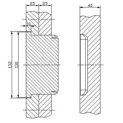
Because it is a small plastic parts, a cavity, and in order to high processing efficiency, convenient disassembly, but also to ensure the shape and size accuracy of plastic parts, the design of the overall convex and concave die selection for the whole. The convex die is processed by the separate processing method, and then pressed into the template with the H7/m6 transition. The schematic diagram of the structure design of the convex and the concave die is as follows:
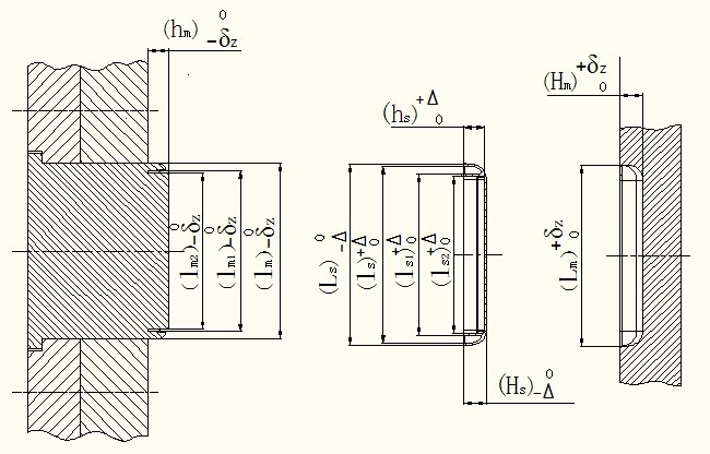
2.5.2 Design and calculation of cavity and core structure
The relationship between the working size of the mold part and the plastic part size is shown below:
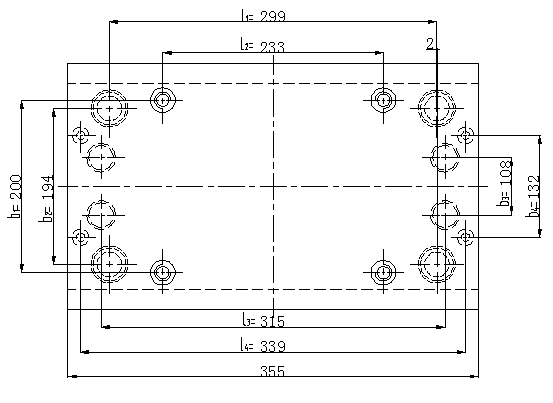
2.6 The choice of mold frame
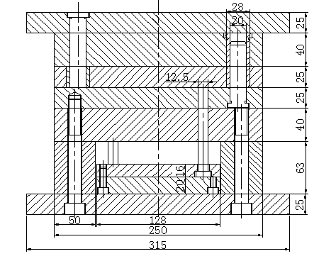
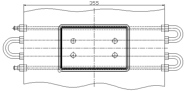
Since this design is for small and medium-sized plastic parts, the mold frame is P4-250355-26-Z1 GB/T12556.1-90, and the B0×L of the mold frame is 250mm×355mm.
The mold assembly diagram is as follows:
2.7 Structural component design
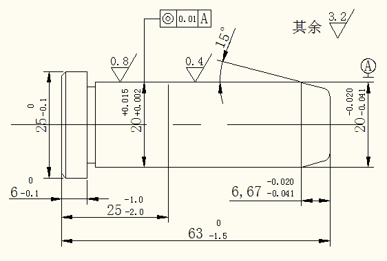
2.7.1 Guide column structure design
The diameter of the guide post is Φ20, and the material selected for the guide post is 20 steel, with carburizing of 0.5~0.8mm and quenching hardness of 56~60HRC. The chamfered Angle shown in the figure is no more than 0.5×450. The guide post is marked as Φ20×63×25(I) — 20 steel GB4169.4 — 84. H7/m6 transition fit is adopted between the fixed part of the guide column and the template. Another guide post is marked Φ20×112×32 — 20 steel GB4169.4 — 84.
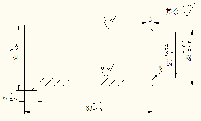
2.7.2 Guide sleeve structure design
The diameter of the guide sleeve is Φ28, and the material of the guide sleeve is 20 steel, carburized 0.5~0.8mm, and the hardness of the quenched treatment is 56~60HRC. The chamfering shown in the figure is no more than 0.5×450. The guide sleeve is marked as Φ20×63(I) — 20 steel GB4169.3 — 84, and the matching accuracy of the guide post and guide sleeve is H7/f7. Another guide sleeve marked Φ20×50(I) — 20 steel GB4169.3 — 84.
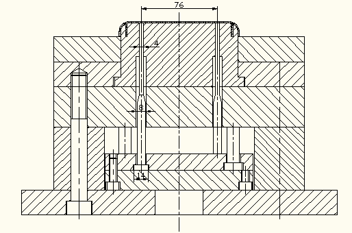
2.8 Launch mechanism design
The pushing mechanism is generally composed of pushing, resetting and guiding.
Because the plastic parts are relatively thin, in the case of trying to ensure the appearance quality of plastic parts, the design of the launch mechanism adopts the ejector rod to push out the plastic parts.
The schematic diagram of the launch mechanism is as follows:
The structure and parameters of the push rod are shown below:
The structural form and parameters of the reset rod are shown below:
2.9 Design of cooling system
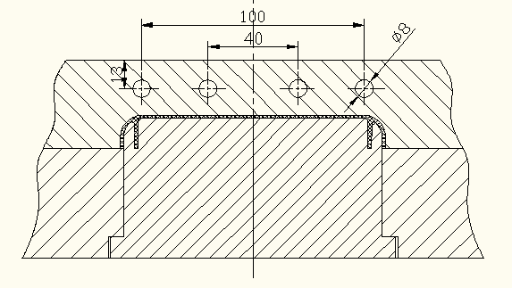
As the cooling is not uniform, the cooling system of the cooling channel should be as much as possible, this design choice for 4. The channel distance from the cavity surface is equal, and the sprue is also strengthened for cooling. The cooling system adopts DC circulation type, which has simple structure and convenient processing.
The cooling system design is as follows:
Part Three:Check calculation of injection mold
3.1.Check related process parameters of injection machine
3.1.1 Check the maximum injection volume
3.1.2 Check the clamping force
3.1.3 Check the mold opening trip
3.2. Check the thickness of side wall and bottom plate of rectangular cavity
3.2.1 Check the side wall thickness of integral rectangular cavity
3.2.2 Check the thickness of integral rectangular cavity bottom plate
conclusion
Freshness Keeper team’s designer Xie Master this design is mainly for the mold design of plastic lunch box cover, through the analysis of the material of plastic lunch box cover, the structure of plastic parts and technology, and then reasonable, scientific completion of the injection mold design.
Freshness Keeper The advantages of the design is to simplify the injection mold mechanism as far as possible to ensure the quality of plastic parts, shorten the molding cycle, lower production costs. The important points of the design are injection molding process, cavity layout, parting surface selection, gating system, ejection mechanism, demoulding mechanism, cooling system, injection molding machine selection and the check of relevant parameters and the design of the main parts.
Freshness Keeper’s special design lies in the design of pouring system, pouring system gate sleeve and positioning ring for a single part, ensure the life of the mold, and material selection, processing, heat treatment and replacement are convenient; The gate is point gate direct type, which requires double parting surface, and the fixed distance drawplate is used to limit the first parting. The structure is simple and reasonable.
Post time: Nov-01-2022